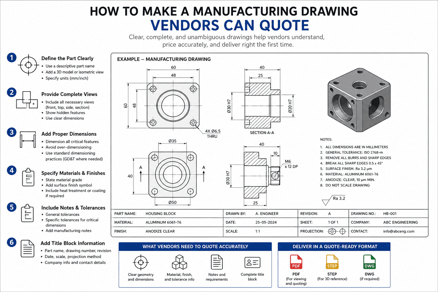
You sent a manufacturer your CAD file and got back a padded quote, an inconsistent one, or a request for more information. The file looked complete, so the response is confusing. The problem is not the model — it is that a 3D model, on its own, does not carry most of what a vendor needs to price the job.
A vendor quotes what they can see and prices everything else as risk. A model shows the geometry and one nominal number for every dimension. It does not say which of those numbers must be held tight and which can drift, what grade of material to use, how the part is finished, or how anyone confirms it came out right.
Left to guess, a vendor either pads the quote to cover the uncertainty or asks you to fill the gaps. This article covers what that missing information is, and how to get it to a vendor in a form they can quote.
Contents
It is the information, not the drawing
The thing a manufacturer actually needs is not a drawing as such. It is a set of answers to five questions:
- What is the geometry, and which dimensions are critical?
- How precise does each critical dimension have to be?
- What material and grade?
- What finish, and on which surfaces?
- How is the part checked to confirm it passed?
That information usually travels as a 2D manufacturing drawing, because most job shops quote from one. But what is mandatory is the information, not the format. A model with the tolerances and callouts embedded in it can work too. The rest of this article is those five answers, one section each.
Dimensions
A model already holds the geometry, so the job here is not redrawing the part. It is stating the critical measurements explicitly and marking which ones matter.
Every part has a few dimensions that carry function — a bearing seat, a mating face, a bolt pattern that has to line up with something else — and many that do not matter beyond looking roughly right. A bare model treats them identically: every dimension is one exact number. A quotable drawing separates them, so the vendor knows where to spend effort and where not to.
Dimension from a datum, not from each other
Pick one fixed reference on the part — an edge or a face — and dimension every feature from that same reference. This is called a datum. Avoid the alternative, chaining measurements one off the next, because the errors compound.
Take a plate with three holes in a row. Dimension it by chaining — hole 1 to hole 2, hole 2 to hole 3 — and each gap carries its own tolerance, say ±0.1 mm. Hole 2's position depends on hole 1 being right. Hole 3's position depends on both. By the third hole, the possible error has stacked up to as much as ±0.3 mm, even though every individual dimension measured within spec. This is how a part passes every check on the drawing and still does not fit whatever it has to bolt to.
Dimension all three holes from one edge instead, and each one is independently within ±0.1 mm of that edge. No stacking, because none of them depend on each other. Datum dimensioning is the default for exactly this reason, and it is worth checking for on any drawing with more than one hole, slot, or feature that has to line up with something else.
State which document governs
A model and a drawing can go out of sync. Someone updates the CAD late in the project and forgets to update the drawing, or updates the drawing and not the model, and now the two disagree on a number.
Put a line on the drawing settling this in advance, typically “dimensions on this drawing govern over the 3D model.” That single line removes the ambiguity for the vendor.
It also means the drawing has to be kept accurate: once it is named as the authority, any number left stale on it is what the vendor builds to, whether or not the model has since moved on.
Tolerances
This is the section that moves your quote the most.
A tolerance is the range a dimension is allowed to fall in. A hole called out as 10.00 mm means nothing on its own. 10.00 mm held to within 0.01 is a precision operation; 10.00 mm within 0.2 is routine. The tighter the tolerance, the more machining time, tooling, inspection, and scrap it costs. Tolerances are where a drawing quietly sets its own price.
The most expensive mistake first-timers make is tolerancing everything tightly, usually by leaving the CAD default in place. It feels safe. It is not. It prices the whole part as if every feature were critical, when only a handful are. The discipline is the opposite: tighten the few dimensions that carry function, and leave the rest to a general tolerance.
That general tolerance is worth setting deliberately. A drawing carries a default tolerance block — a blanket “unless stated otherwise” value that applies to every dimension you did not call out specifically. Set it to something reasonable for the part, tighten only what needs it, and you have communicated the whole cost picture without touching most of the dimensions.
GD&T, and when you can skip it
Most simple parts do not need geometric dimensioning and tolerancing (GD&T), and if that describes your part, skip to the next section.
GD&T is a system for controlling relationships between features, not just their sizes: how flat a surface is, how true a hole is to a reference, how concentric two diameters are to each other. Plain dimensions and tolerances control how big things are; GD&T controls how they relate. You need it when a part has to fit or seal against another part to a defined standard, and the relationship, not just the size, is what matters.
A bracket, a spacer, or a simple enclosure usually does not. A bearing housing, a sealing flange, or a mating pair usually does. If you are unsure, this is a good thing to hand to someone who can tell you which few callouts the part actually needs, rather than applying them everywhere and paying for it.
Material and finish
Specify the grade, not the metal. For example, “Aluminium” is not a specification; 6061-T6 is. The grade changes strength, machinability, corrosion resistance, and cost, and a vendor cannot quote or buy material without it. The same holds for plastics and steels: name the actual grade.
Finish needs the same precision, plus one thing people forget: which surfaces it applies to. State the finish — anodising, plating, powder coat, bead blast, as-machined — and call out whether it covers the whole part or only certain faces. Ambiguity here is a common cause of parts that are technically correct and still wrong.
Inspection: how the vendor knows it passed
A drawing that says what to make should also make clear how anyone confirms it was made right. In practice this means flagging the critical dimensions you want inspected and measured, rather than leaving the vendor to decide what matters.
This is also what you check against when parts arrive. The dimensions you mark for inspection here are the ones that go into first article inspection on delivery — the first-off part measured against the drawing before a full run is approved. A drawing with clear inspection intent and a first article check on arrival are the two ends of the same control.
How to actually get a quotable drawing made
Knowing what belongs on a drawing is not the same as producing one. There are three paths, depending on where you are.
- You annotate it yourself. If you can produce a dimensioned drawing from your model and now know what to put on it, this is the cheapest route. It suits simple parts and people comfortable in CAD.
- You have the drawing produced from your model. If you have a model but do not draft, or do not want to, someone can turn it into a fully documented, quotable drawing. You supply the model and the intent — what is critical, target material, finish, quantity — and they produce the drawing. This is the common path for founders who have a design but not a drafting background.
- The vendor works from an annotated model. Some manufacturers will quote from a model with the tolerances and callouts embedded, with no separate 2D drawing. This is less common among smaller Indian job shops, but PaaS platforms like EsyProcure can work from a 3D model with tolerances and callouts embedded.
Complex or tightly functional parts — sealing surfaces, precise mating pairs, anything where GD&T is doing real work — are worth having drawn by someone who does it regularly, because on those parts a weak drawing is what costs you later.
Pre-send checklist
Before you send a drawing out for quotes, confirm it has:
- Critical dimensions stated and dimensioned from a clear datum
- The dimensions that carry function marked as critical
- A tolerance on every critical dimension, and a sensible default tolerance block for the rest
- GD&T callouts only where a relationship genuinely has to be controlled
- Material grade specified, not just the material
- Finish specified, with the surfaces it applies to
- The dimensions you want inspected flagged
- Quantity, so the vendor can quote at the right volume
If all eight are present, a vendor can give you a firm, comparable quote instead of a padded guess.
FAQ
Can't I just send the CAD file?
Sometimes, but usually not for an accurate quote. The model carries geometry, not tolerances, criticality, material grade, finish, or inspection intent. Without those a vendor pads the price or comes back with questions.
Do I need GD&T?
Most simple parts do not. Use it only where the relationship between features has to be controlled to a standard — a fit, a seal, a precise mating pair. Applying it everywhere raises cost for no benefit.
What's the most expensive mistake on a drawing?
Tolerancing everything tightly, usually by leaving the CAD default in place. It prices the whole part as if every feature were critical. Tighten only what carries function.
I have a model but can't make a drawing. Am I stuck?
No. A quotable drawing can be produced from your model. You supply the model and the intent — critical features, material, finish, quantity — and the documentation is done from there by a firm that specialises in making drawings.
Drawing or annotated model — which do vendors want?
Most smaller job shops quote from a 2D drawing. Others, like EsyProcure, accept a model with embedded tolerances and callouts.